After doing a couple of projects in assembly, I’ve started over again in C, but this time I’ll be publishing the projects. The purpose of this is to:
- Figure out how the usual C code translates into assembly and vice versa.
- Provide a series of simple projects building on each other for people interested in microcontrollers.
- Give employers some public examples to look through.
- Get started building an awesome project for Christmas gifts.
To start off this series of posts, I’ll use the simplest example possible, which is blinking an LED. I’ll be using the avr-gcc toolchain to compile. The microcontroller I’ll be using is the Atmel AVR ATtiny2313 until I start to run out of space or pins. Unless an example requires it, the fuses will be set so that the microcontroller runs at 1MHz.
Hooking It Up

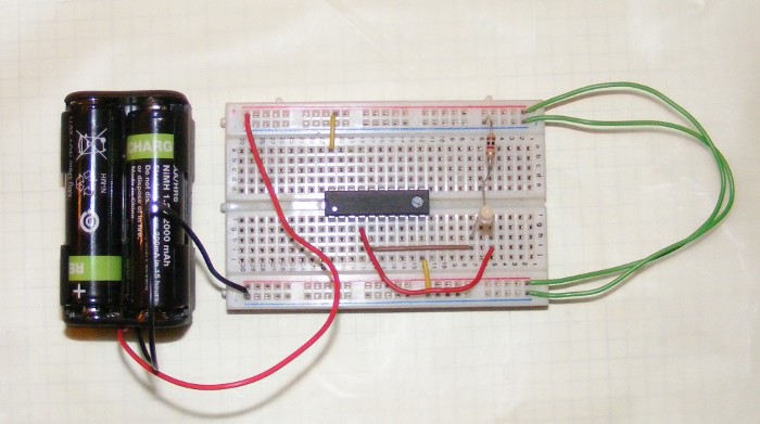
I have a two color LED with the common cathode connected to ground by a 1kΩ resistor. The two anodes are hooked up to the PA0 and PA1 pins on the microcontroller. It doesn’t matter which color is hooked up to which pin for this example. Since I don’t have a good bench power supply available, the microcontroller is powered by a 4xAA battery pack which provides around 5-5.3V (right under the maximum operating voltage of 6.0V for the microcontroller.)
The Terminology
Fuses - To change clockspeed and other basic features such as using the reset pin as IO, AVR microcontrollers uses fuses that are set when programming. Other microncontrollers may do things differently, right now my only experience has been with AVRs that uses fuses and a Freescale HCS08 chip where the clock was set in code. The fuse calculator provided by Engbedded is what I personally use to calculate what I need to set. Fuses only need to be set once, even if you program the chip multiple times.
Anode/Cathode - An anode is where current flows into an element, the cathode is where it flows out. In the LED I’m using, there is a common cathode, so I only need to connect that to ground (with the resistor of course). The two anodes of the LED are connected to their respective pins.
Design Considerations
One thing to note about using _delay_ms() is the resolution. From the <util/delay.h> reference page.
The maximal possible delay is 262.14 ms / F_CPU in MHz.
Uhoh. With our clock set at 1 MHz, this means the max delay is 262.14ms, just over a quarter of a second.
However,
When the user request delay which exceed the maximum possible one, _delay_ms() provides a decreased resolution functionality.

In this mode _delay_ms() will work with a resolution of 1/10 ms, providing delays up to 6.5535 seconds (independent from CPU frequency).

The user will not be informed about decreased resolution.
This isn’t a problem, since we don’t need such a small resolution.
But finally,
If the avr-gcc toolchain has __builtin_avr_delay_cycles(unsigned long) support, maximal possible delay is 4294967.295 ms/ F_CPU in MHz.
For values greater than the maximal possible delay, overflows results in no delay i.e., 0ms.
Checking /usr/lib/avr/include/avr/builtins.h, this builtin is defined along with the accompanying __HAS_DELAY_CYCLES macro. So there’s nothing to worry about in the first place.
The Code
#include <avr/io.h>
#include <util/delay.h>

#define F_CPU 1000000UL // 1MHz

int main(void)
{
    DDRA |= 0x03; // Set PA0 and PA1 to be outputs
    while (1)
    {
        PORTA ^= 0x03; // Toggle PA0 and PA1
        _delay_ms(1000.0);
    }
}
If the microcontroller is programmed properly, the LED should be flashing a combination of the two colors (an orange-y color in my case).