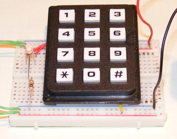
For this project, I’m going to introduce a 4x3 (3x4?) keypad. The 0-9 keys will determine the frequency of the flashing LED, from 0Hz to 9Hz. In addition, the * and # keys will determine which LED I’m setting the frequency for.
The Terminology
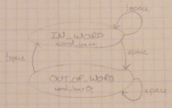
State Machine - A state machine is a collection of different states. For example, you could have two states IN_WORD and OUT_OF_WORD, which both process a string. While in the IN_WORD state, you could, for example, increment a word length counter. When a space appears, you’ll set the state to OUT_OF_WORD. While you’re in the OUT_OF_WORD state, you could set the word length counter to 0, but when you encounter something that’s not a space, you switch to the state IN_WORD.
Debounce - One annoying feature of keypads and switches in general is that when they’re pressed they will bounce from open to closed. To account for this, my code has a built in delay in the state machine to filter out rapid changes that would come from debouncing.
Design Considerations
There are two main parts to this project:
- Keypad Entry
- LED Flashing
There’s a fairly simple state machine that I can implement to decode the key presses. (The one in the code has been modified a bit from the picture to loop in decode_state a bit to debounce the keypad, but is basically the same.)
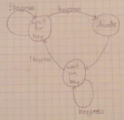
Once a key is decoded, I’ll stick it in a buffer so it can be processed in the main loop.
To get LED flashing correct, the timer will be set to interrupt so all of the toggle frequencies are multiples of the interrupt frequency. The exact multiples will be stored in a lookup table indexed by the keypad numbers.
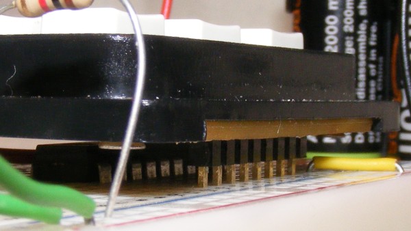
Working With the Keypad
The 3x4 keypad has 8 pins. 4 pins are for the rows and 3 for the columns, along with one pin that won’t be connected. There are a couple of ways to decode it, but since I have plenty of free pins, I’ll hook them all up to a port and continuously poll that for changes and then scan it for the row/column combination. When a button on the keypad is pressed, it connects the corresponding row and column lines. So what I’ll do is set the pins connected to the row lines as inputs with the pullup resistor enabled (this sets them high when there’s no other signal). The pins connected to the column lines will be set as outputs and all will be set low. When a button is pressed, a single one of the row inputs will also go low. Once this change is detected, then for each column I toggle the output high until I find one that makes all of the rows read high. Then I use the column number as an index into a short lookup table to determine which button was pressed. The code should make the process clear!
Getting the Right LED Frequency
To simplify matters, I’m going to use a separate timer for LED flashing interrupts. I’ve decided the interrupt should trigger every millisecond. This isn’t perfect for all frequencies. However, the greatest calculated error is only .2% for 6Hz, which is acceptable because I won’t be able to tell the difference with my eye. (For reference, the errors from 1Hz to 9Hz are: 0%, 0%, .1%, 0%, 0%, .2%, .1%, 0%, .1%).
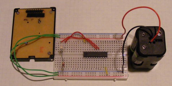
Hooking It Up
The Code
Unfortunately code length is quickly growing larger than I want to keep directly in the blog post. If you want syntax highlighting, you’ll have to open it into the editor of your choice.